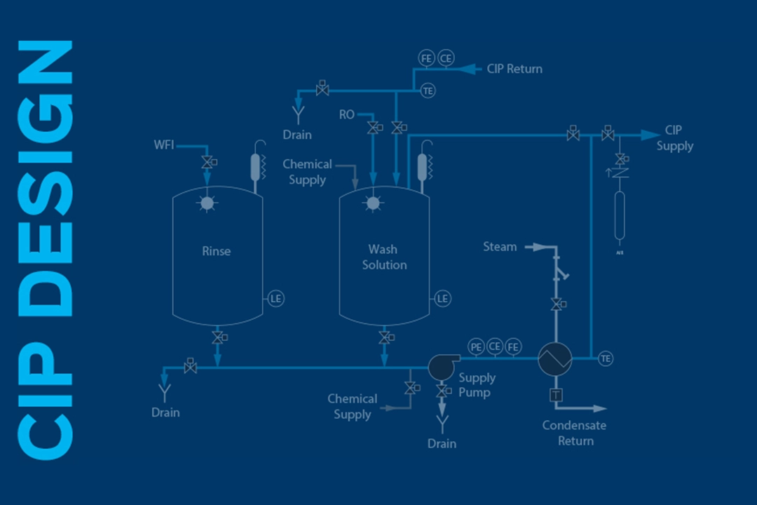
Pharmaceutical manufacturing process equipment such as bioreactors, fermenters and process piping are generally cleaned using a strategic CIP system design that meets ASME-BPE standards. The most efficient, effective and hygienic results are achieved when the CIP system design is considered during the preliminary stages of the facility’s entire process design.
“Pharmaceutical manufacturers must perform frequent cleaning of their process equipment’s interior surfaces to meet stringent regulations,” said Chris McNulty, Sani-Matic’s director of key accounts, bio-pharm. “For those with bioreactors, fermenters and other vessels, CIP plays an important role in optimizing the cleaning and validation processes.”
First Things First
Designing a CIP system begins by sizing the CIP system for sufficient flow and pressure to thoroughly remove residue, reduce cycle times, and rinse effectively.
Determining proper flow and pressure is dictated by the spray devices and process lines.
Static spray balls are the most common spray device used in pharmaceutical CIP applications. And, to determine the required flow and pressure needed to clean a vessel with a static spray ball, you multiply the circumference of the vessel in feet by three gallons per minute (gpm) per foot of circumference to create a flow turbulence to clean the vessel’s interior. “If there are multiple spray balls within a vessel, make sure you take into consideration that each one must receive 25-30 psi,” stated McNulty.
Although not as common, some processes with heavier soil loads may require rotating impingement spray devices, which are commonly sized for 1.5 gpm per foot of circumference at 60 psi or greater.
In addition to spray devices, when determining flow and pressure, attention must be given to pipe line diameters and lengths to maintain a velocity of five feet per second. The flow rate needed to attain this velocity is determined by the line diameter. See Table 1: Pipeline flow rate (velocity).
The distance from the vessel to the CIP system also impacts pressure requirements.
Table 1: Pipeline flow rate (velocity)
| Tube OD | Tube ID | Gallons Per Minute (gpm) for 5 Feet/Second |
| 0.5” | 0.37” | 2 gpm |
| 0.75” | 0.62” | 5 |
| 1.0” | 0.87” | 10 |
| 1.5” | 1.37” | 23 |
| 2.0” | 1.87” | 43 |
| 2.5” | 2.37” | 69 |
| 3.0” | 2.87” | 101 |
| 4.0” | 3.834” | 180 |
| 6.0” | 5.834” | 417 |
Think Goals and Location, Early and Often for CIP System Design
When implementing a CIP system, think about what the best CIP system design is for your process goals and where the system will be located—and consider them at the beginning of your project.
“If speed of operation is important, a stationary two-tank system with separate solution and rinse tank will operate faster than a one-tank system,” explained McNulty. “But that means appropriate space and utilities must be available.”
If a portable CIP system is needed, it is limited to a one-tank design, but eliminates the need for permanent CIP supply and return piping by using flexible hoses. McNulty noted, “Both stationary and portable designs will need to allow sufficient space for clearances to meet maintenance and local code requirements.”
Room classification will also be considered during CIP system design. Hazardous locations, such as Class I, Div 1, for example, require specialized electrical components and a purging system for the panel to meet safety requirements.
Drains are Critical for a CIP Cycle
Discharging to drain is part of a CIP cycle and requires thought. Drain utilities must be capable of handling high discharge temperatures equal to CIP temperatures, unless cooled by additional utilities. And, flow rates equal to the highest CIP circuit flow rate will be seen at the drain. One more consideration regarding drains is the pH of discharge solution, which varies depending on cleaning chemicals and soil. Because many local ordinances put limitations on discharge pH, it should be addressed during design.
The Brains of the Operation
Finally, most bioreactor and fermenter control systems require a means of communication with the CIP system to signal valve cycling, agitator operation, alarm conditions and cycle completion. Whether through low-voltage signals or over Ethernet, it’s important to determine these requirements early in the project design.
These are just some factors to contemplate when designing pharmaceutical CIP systems for a validatable process. For an optimized system and desired cleaning results for your pharmaceutical equipment, consider how the CIP system will fit into your process at the beginning of your project.


